

توضیحات محصول
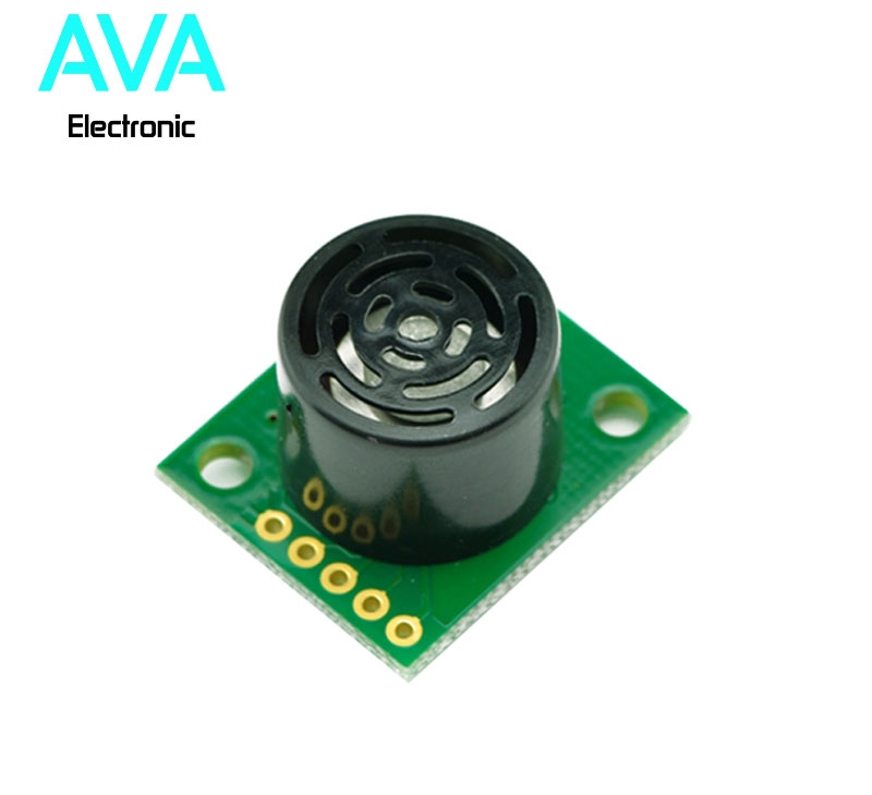
SRF02 Ultrasonic range finder
The SRF02 is a single transducer ultrasonic rangefinder in a small footprint PCB. It works well for range finding or object detection with a range between approx 15cm and 2.5m.
It features both I2C and a Serial interfaces.The serial interface is a standard TTL level UART format at 9600 baud, and may be connected directly to the serial ports on any microcontroller. Up to 16 SRF02’s may be connected together on a single bus, either I2C or Serial. New commands in the SRF02 include the ability to send an ultrasonic burst on its own without a reception cycle, and the ability to perform a reception cycle without the preceding burst. This has been as requested feature on our sonar’s and the SRF02 is the first to see its implementation. Because the SRF02 uses a single transducer for both transmission and reception, the minimum range is higher than our other dual transducer rangers. The minimum measurement range varies from around 17-18cm (7 inches) on a warm day down to around 15-16cm (6 inches) on a cool day. Like all our rangefinders, the SRF02 can measure in uS, cm or inches.
- Minimum range approx 15cm
- Maximun Range approx 2.5m
- I2C and Serial interfaces
There are two operating modes for the SRF02. I2C mode and Serial Mode. This is set with the Mode pin, connected to 0v Ground for Serial Mode and left unconnected (or tied to +5v Vcc) for I2C Mode.
I2C Communication
To use the SRF02 in I2C mode, make sure nothing is connected to the mode pin, it must be left unconnected.
The default shipped address of the SRF02 is 0xE0. It can be changed by the user to any of 16 addresses E0, E2, E4, E6, E8, EA, EC, EE, F0, F2, F4, F6, F8, FA, FC or FE, therefore up to 16 sonar’s can be used.
Connections

Registers
The SRF02 appears as a set of 6 registers.
Location | Read | Write |
۰ | Software Revision | Command Register |
۱ | Unused (reads 0x80) | N/A |
۲ | Range High Byte | N/A |
۳ | Range Low Byte | N/A |
| ۴ | Autotune Minimum – High Byte | N/A |
| ۵ | Autotune Minimum – Low Byte | N/A |
Only location 0 can be written to. Location 0 is the command register and is used to start a ranging session. It cannot be read. Reading from location 0 returns the SRF02 software revision. The ranging lasts up to 65mS, and the SRF02 will not respond to commands on the I2C bus whilst it is ranging.
Locations, 2 and 3, are the 16bit unsigned result from the latest ranging – high byte first. The meaning of this value depends on the command used, and is either the range in inches, or the range in cm or the flight time in uS. A value of 0 indicates that no objects were detected. Do not initiate a ranging faster than every 65mS to give the previous burst time to fade away.
Locations, 4 and 5, are the 16bit unsigned minimum range. This is the approximate closest range the sonar can measure to. See the Autotune section below for full details.
Commands
The are three commands to initiate a ranging (80 to 82), to return the result in inches, centimeters or microseconds. Another set of three commands (86 to 88) do the same, but without transmitting the burst. These are used where the burst has been transmitted by another sonar. It is up to you to synchronize the commands to the two sonar’s. There is a command (92) to transmit a burst without doing the ranging and also a set of commands to change the I2C address.
| Command | Action | |
| Decimal | Hex | |
| ۸۰ | ۰x50 | Real Ranging Mode – Result in inches |
| ۸۱ | ۰x51 | Real Ranging Mode – Result in centimeters |
| ۸۲ | ۰x52 | Real Ranging Mode – Result in micro-seconds |
| ۸۶ | ۰x56 | Fake Ranging Mode – Result in inches |
| ۸۷ | ۰x57 | Fake Ranging Mode – Result in centimeters |
| ۸۸ | ۰x58 | Fake Ranging Mode – Result in micro-seconds |
| ۹۲ | ۰x5C | Transmit an 8 cycle 40khz burst – no ranging takes place |
| ۹۶ | ۰x60 | Force Autotune Restart – same as power-up. You can ignore this command. |
| ۱۶۰ | ۰xA0 | ۱st in sequence to change I2C address |
| ۱۶۵ | ۰xA5 | ۳rd in sequence to change I2C address |
| ۱۷۰ | ۰xAA | ۲nd in sequence to change I2C address |
Ranging
To initiate a ranging, write one of the above commands to the command register and wait the required amount of time for completion and read the result. The echo buffer is cleared at the start of each ranging. The ranging lasts up to 66mS, after this the range can be read from locations 2 and 3.
Checking for Completion of Ranging
You do not have to use a timer on your own controller to wait for ranging to finish. You can take advantage of the fact that the SRF02 will not respond to any I2C activity whilst ranging. Therefore, if you try to read from the SRF02 (we use the software revision number a location 0) then you will get 255 (0xFF) whilst ranging. This is because the I2C data line (SDA) is pulled high if nothing is driving it. As soon as the ranging is complete the SRF02 will again respond to the I2C bus, so just keep reading the register until its not 255 (0xFF) anymore. You can then read the sonar data. Your controller can take advantage of this to perform other tasks while the SRF02 is ranging. The SRF02 will always be ready 70mS after initiating the ranging.
LED
The red LED is used to flash out a code for the I2C address on power-up (see below). It also gives a brief flash during the “ping” whilst ranging.
Changing the I2C Bus Address
To change the I2C address of the SRF02 you must have only one sonar on the bus. Write the 3 sequence commands in the correct order followed by the address. Example; to change the address of a sonar currently at 0xE0 (the default shipped address) to 0xF2, write the following to address 0x00; (0xA0, 0xAA, 0xA5, 0xF2 ). These commands must be sent in the correct sequence to change the I2C address, additionally, No other command may be issued in the middle of the sequence. The sequence must be sent to the command register at location 0, which means ۴ separate write transactions on the I2C bus. When done, you should label the sonar with its address, however if you do forget, just power it up without sending any commands. The SRF02 will flash its address out on the LED. One long flash followed by a number of shorter flashes indicating its address. The flashing is terminated immediately on sending a command the SRF02.
| Address | Long Flash | Short flashes | |
| Decimal | Hex | ||
| ۲۲۴ | E0 | ۱ | ۰ |
| ۲۲۶ | E2 | ۱ | ۱ |
| ۲۲۸ | E4 | ۱ | ۲ |
| ۲۳۰ | E6 | ۱ | ۳ |
| ۲۳۲ | E8 | ۱ | ۴ |
| ۲۳۴ | EA | ۱ | ۵ |
| ۲۳۶ | EC | ۱ | ۶ |
| ۲۳۸ | EE | ۱ | ۷ |
| ۲۴۰ | F0 | ۱ | ۸ |
| ۲۴۲ | F2 | ۱ | ۹ |
| ۲۴۴ | F4 | ۱ | ۱۰ |
| ۲۴۶ | F6 | ۱ | ۱۱ |
| ۲۴۸ | F8 | ۱ | ۱۲ |
| ۲۵۰ | FA | ۱ | ۱۳ |
| ۲۵۲ | FC | ۱ | ۱۴ |
| ۲۵۴ | FE | ۱ | ۱۵ |
Take care not to set more than one sonar to the same address, there will be a bus collision and very unpredictable results.
Note – there is only one module address stored in the SRF02. If you change it, the equivalent Serial Mode address will also change:
۰xE0, 0xE2, 0xE4, 0xE6, 0xE8, 0xEA, 0xEC, 0xEE, 0xF0, 0xF2, 0xF4, 0xF6, 0xF8, 0xFA, 0xFC, 0xFE I2C addresses
۰x00, 0x01, 0x02, 0x03, 0x04, 0x05, 0x06, 0x07, 0x08, 0x09, 0x0A, 0x0B, 0x0C, 0x0D, 0x0E, 0x0F Equivalent Serial addresses
Serial Communication
To use the SRF02 in Serial mode, make sure the Mode pin is connected to 0v Ground.
Serial data is fixed at 9600 baud. To communicate with the SRF02, you simply need to send two bytes, the address of the SRF02 (factory default is 0) and the command. The default shipped address can be changed by the user to any of 16 addresses 0, 1, 2, 3, 4, 5, 6, 7, 8, 9, 10, 11, 12, 13, 14, or 15, therefore up to 16 sonar’s can be used.
Connections
The connections to the SRF02 are shown below. The “Mode” pin must be connected to 0v ground to place the SRF02 in serial mode. The Rx pin is data into the SRF02 and should be connected to the Tx pin on your controller. The Tx pin is data out of the SRF02 and should be connected to the Rx pin on your controller. If you’re using multiple SRF02’s, you can connect them all up to the same serial port on your controller. Connect the Tx from your controller to all the Rx pins on the SRF02’s and connect the Rx pin on your controller to all the Tx pins on the SRF02’s. This works because the Tx pins are high impedance (just a weak pull-up to 5v), except when actually sending data. Just make sure all the SRF02’s are programmed to different addresses.

Commands
To send a command to the SRF02, you need to send two bytes. The first is the SRF02’s address 0 to 15, (0x00 to 0x0F) and then the actual command itself – see below. There are three commands to initiate a ranging (80 to 82), to produce the result in inches, centimeters or microseconds. These three commands don’t Tx the result back to your controller. You should wait 70mS and then use command 94 to get the result of the ranging. Another set of three commands (83 to 85) do the same, but also transmits the result of the ranging back to your controller as soon as it is available. Together, these six commands (80 – 85) are called “Real” because they perform a complete ranging. There is another set of six commands (86 – 91) called “Fake”. They are the same as the “Real” commands except that they do not send the 8-cycle burst out. These are used where the burst has been transmitted by another sonar. It is up to you to synchronize the commands to the two sonar’s. There is a command (92) to transmit a burst without doing the ranging.
Command 93 is used to get the firmware revision of the SRF02.
Command 94 gets returns two bytes (high byte first) from the most recent ranging. Put them together to make a 16-bit result.
Commands 95 and 96 are used by the Autotune algorithms.
| Command | Action | |
| Decimal | Hex | |
| ۸۰ | ۰x50 | Real Ranging Mode – Result in inches |
| ۸۱ | ۰x51 | Real Ranging Mode – Result in centimeters |
| ۸۲ | ۰x52 | Real Ranging Mode – Result in micro-seconds |
| ۸۳ | ۰x53 | Real Ranging Mode – Result in inches, automatically Tx range back to controller as soon as ranging is complete. |
| ۸۴ | ۰x54 | Real Ranging Mode – Result in centimeters, automatically Tx range back to controller as soon as ranging is complete. |
| ۸۵ | ۰x55 | Real Ranging Mode – Result in micro-seconds, automatically Tx range back to controller as soon as ranging is complete. |
| ۸۶ | ۰x56 | Fake Ranging Mode – Result in inches |
| ۸۷ | ۰x57 | Fake Ranging Mode – Result in centimeters |
| ۸۸ | ۰x58 | Fake Ranging Mode – Result in micro-seconds |
| ۸۹ | ۰x59 | Fake Ranging Mode – Result in inches, automatically Tx range back to controller as soon as ranging is complete. |
| ۹۰ | ۰x5A | Fake Ranging Mode – Result in centimeters, automatically Tx range back to controller as soon as ranging is complete. |
| ۹۱ | ۰x5B | Fake Ranging Mode – Result in micro-seconds, automatically Tx range back to controller as soon as ranging is complete. |
| ۹۲ | ۰x5C | Transmit an 8 cycle 40khz burst – no ranging takes place |
| ۹۳ | ۰x5D | Get software version – sends a single byte back to the controller |
| ۹۴ | ۰x5E | Get Range, returns two bytes (high byte first) from the most recent ranging. |
| ۹۵ | ۰x5F | Get Minimum, returns two bytes (high byte first) of the closest range measurable – see Autotune section |
| ۹۶ | ۰x60 | Force Autotune Restart – same as power-up. You can ignore this command. |
| ۱۶۰ | ۰xA0 | ۱st in sequence to change I2C address |
| ۱۶۵ | ۰xA5 | ۳rd in sequence to change I2C address |
| ۱۷۰ | ۰xAA | ۲nd in sequence to change I2C address |
LED
The red LED is used to flash out a code for the I2C address on power-up (see below). It also gives a brief flash during the “ping” whilst ranging.
Changing the SRF02 Address
To change the address of the SRF02 you must have only one sonar connected. Write the 3 sequence commands in the correct order followed by the address. Example; to change the address of a sonar currently at 0 (the default shipped address) to 5, write the following to address 0; (0xA0, 0xAA, 0xA5, 0x05 ). These commands must be sent in the correct sequence to change the I2C address, additionally, No other command may be issued in the middle of the sequence. The sequence must be sent as four separate commands to the current address of the sonar. i.e. 0x00, 0xA0 then 0x00, 0xAA, then 0x00, 0xA5 and finally 0x00, 0x05. When done, you should label the sonar with its new address, however if you do forget, just power it up without sending any commands. The SRF02 will flash its address out on the LED. One long flash followed by a number of shorter flashes indicating its address. The flashing is terminated immediately on sending a command the SRF02.
| Address | Long Flash | Short flashes | |
| Decimal | Hex | ||
| ۰ | ۰۰ | ۱ | ۰ |
| ۱ | ۰۱ | ۱ | ۱ |
| ۲ | ۰۲ | ۱ | ۲ |
| ۳ | ۰۳ | ۱ | ۳ |
| ۴ | ۰۴ | ۱ | ۴ |
| ۵ | ۰۵ | ۱ | ۵ |
| ۶ | ۰۶ | ۱ | ۶ |
| ۷ | ۰۷ | ۱ | ۷ |
| ۸ | ۰۸ | ۱ | ۸ |
| ۹ | ۰۹ | ۱ | ۹ |
| ۱۰ | ۰A | ۱ | ۱۰ |
| ۱۱ | ۰B | ۱ | ۱۱ |
| ۱۲ | ۰C | ۱ | ۱۲ |
| ۱۳ | ۰D | ۱ | ۱۳ |
| ۱۴ | ۰E | ۱ | ۱۴ |
| ۱۵ | ۰F | ۱ | ۱۵ |
Take care not to set more than one sonar to the same address, there will be a bus collision and very unpredictable results.
AutoTune
The SRF02 does not require any user calibration. You power up and go right ahead and use the SRF02.
Internally, there are tuning cycles happening automatically in the background. After the ultrasonic burst has been transmitted, the transducer keeps on ringing for a period of time. It is this ringing which limits the closest range the SRF02 can measure. This time period varies with temperature and from transducer to transducer, but is normally the equivalent of 11 to 16cm (4″ to 6″), a bit more if the transducer is warm. The SRF02 is able to detect the transducer ring time and move its detection threshold right up to it, giving the SRF02 the very best performance possible. On power up, the detection threshold is set to 28cm (11″). The tuning algorithms quickly back this right up to the transducer ring. This happens within 5-6 ranging cycles – less than half a second at full scan speed. After this the tuning algorithms continue to monitor the transducer, backing the threshold up even further when possible or easing it out a bit when necessary. The tuning algorithms work automatically, in the background and with no impact on scan time.
The minimum range can be checked, if required by reading registers 4 and 5. This value is returned in uS, cm or inches, the same as the range. It is also possible to make the SRF02 re-tune by writing command 96 but you can ignore this command. It is used during our testing.


همه نقد ها
هیچ دیدگاهی نوشته نشده است.